Vintage Valve Cover Lamp – The Custom DIY Lamp for Car Lovers
Since making our first valve cover lamp, the market has gone crazy over them.
Everyone – and we mean EVERYONE – has loved them and commented on how unique and incredible they are.
Simplistic in design, its sleek industrial look will catch the eye of anyone who sees it.
And while it is simple in concept, there are more than a few tricks that you need to be aware of when it comes to making one.
You can see examples of the finished products at http://thehardycollection.com and there’s also a more in depth DIY manual there as well if you need it.
So let’s get into it.
Tool List
The beauty of this project is that you don’t need many tools to complete it.
We recommend the following list of tools, which you can preview by click on each of the links below. Some of the links on this page are affiliate links and as an Amazon Associate I might earn a tiny amount from qualifying purchases if you end up buying something through one of them.
The tools that you will need are:
- Cordless drill
- 1.25” Hole saw (Inch and one-eighth holesaw) – or whatever size you need to accommodate your pipe.
- Arbor adapter for the cordless drill to use the 1.25” holesaw
- Exacto Knife
- Wire cutters/strippers (optional)
- Countersink bit – ½” 82 degree countersink for use on metal
- Tape measure
- Eye protection
- Masking tape
- Electrical tape
- ¼” metal drill bit at least 3-4” long (enough to drill thru your harmonic balancer)
- JB Weld
You can click on the links above to see examples of what we are recommending if you don’t already have them.
The Valve Cover
As each valve cover is unique, it’s a good idea for you to start with the valve cover itself.
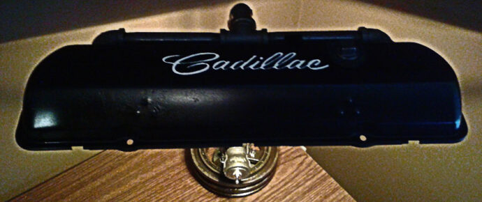
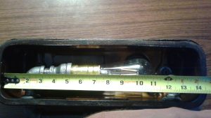
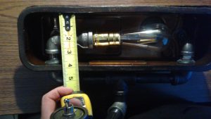
For the size of lamp and material we are recommending here, we suggest you find a valve cover that is no less than 14” long by 3.75” wide on the inside of the valve cover as shown in the pictures below.
In our experience just about any domestic vintage valve cover will work from Cadillac, Corvette, Chevrolet, Ford and so on. Import valve covers are often different shapes and as a result you will have to inspect each of them on a case by case basis before buying them.
To source your valve cover, we recommend looking through the available inventory at auto wreckers in your area (or you could call them), visiting swap meets or looking online at websites like Craigslist or Ebay.
Once you have your valve cover, you can start to gather the rest of the parts needed to make your lamp.
So let’s look at the parts list for this project.
The Parts List
Here is the list of parts that you will need to get for your project.
| Item | Qty | Location |
| Valve Cover | 1 | Main Light Cover |
| Harmonic Balancer | 1 | Base of Light. You can use almost any style, so long as the inside diameter of the harmonic balancer is big enough so your pipe parts can go thru it. |
| Steel Pipe Parts As Shown | ||
| Black Keyless Socket (no switch) | 1 | Sits inside the pipe to hold light bulb. You can get one here. |
| 18ga lamp wire 18/2 SPT-2 black stranded | 10 feet | Inside pipe. |
| Plug to be wired with lamp wire | 1 | At end of wire that comes out of lamp base to plug into the wall. You can get the plug here. |
| On off Toggle Switch | 1 | |
| 1/4″ Flathead bolts and nuts | 3 | Holds floor flange onto the harmonic balancer |
| LED lightbulb | 1 | Length is determined by valve cover size – in most cases less than 8”. You can find these at almost any hardware store or online at a place like Ali Express or Amazon |
| Rubber Grommets | 2 | To put inside the holes in the valve cover to reduce metal on metal contact.
|
| Semi-Gloss Clear Spray Paint | 1 | Can of clear to coat the metal pipe. |
| JB Weld | 1 | To hold toggle switch and washer in place. |
Here are links to some of the parts above:
Click here for the black plastic keyless lampholder.
Click here for the closest version of the ON/OFF switch we could find online.
The majority of these parts can be found at your local hardware store like Home Depot, Lowes, or you can always purchase them online if you need to.
Here are some pictures to go along with the above list for visual representation.
You can change/modify or substitute the various pipe parts to suit your design.
At this point, you will have found a suitable valve cover, have the tools that you need and have purchased the list of parts required above and are ready to start putting everything together.
Assembly and Construction
The first step is to clean all of the oil off of the pipe and harmonic balancer and dry them off.
Wiping the parts off in hot soapy water can often do the trick, and using a wire brush to scrub them off speeds up the process.
Make sure that you have all of the oil and any residue from any glue removed from the parts.
Once they are clean, dry them and then immediately coat them with the semi-gloss clearcoat spray paint. Don’t apply the clearcoat to the threads (or if you do, use as light a coat as possible) as it will make threading the parts together much more difficult.
Once the oil is removed from the pipe, it can start to rust almost instantly. This is called “flash rusting.”
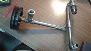
Then, when you have coated all of the pipe parts and are happy with how they look (and they have dried completely – usually 30-60 minutes after coating depending on how heavy you coated it) you are ready to assemble the parts as shown in the picture above.
When assembling the lamp make sure that you tighten the pipe parts as tight as you can while at the same time making sure that the 90 degree elbows are facing the same way and are parallel. You can always add some of the white plumber’s tape or pipe tape to the threads at final assembly to make the connection tighter. Just remember – if you screw the parts in differently on final assembly after you’ve already cut the holes in your valve cover, you stand a good chance of things not fitting properly.
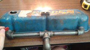
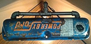
For the “Powered by Ford” lamp, we had no choice but to put the writing backwards as mounting it the other way would have caused the valve cover to come too far forward blocking the light from the lamp, and the writing would have been on the back side and angled away from a person’s view when they looked at the top.
So take your time in laying out your holes. You want them to be within 1/16” if at all possible. If you don’t get this right, you may be able to salvage the project by either shaving the inside of the rubber grommets out with an exacto knife or by not using grommets at all.
The rubber grommets aren’t totally necessary, but I think they provide a nice little finishing touch to cover the ragged holes left by the holesaw and stop the cover from rattling against the pipe parts when complete.
As for the height placement of your holes, you want to make sure that the outside diameter of the grommets will be able to sit above the bottom valve cover lip. We have found that placing the hole in the center of the valve cover (or slightly higher) will generally work best. But make sure you are placing the hole in such a way as to allow the light fixture to work correctly.
Use a holesaw slightly larger than the outside diameter of your pipe to make your holes.
We have found that if you cover the approximate area with making tape you can mark with a pencil exactly where you want your hole to be.
We suggest making your holes in the valve cover before you paint and or clearcoat your valve cover as if you do this afterward, it can cause the paint to chip/scratch. And while the outside of the grommets can hide a little of this, if the paint chips beyond what the grommet covers, you will have to go back and touch up the paint.
Once you have your holes cut, you can put the grommets into the holes and assemble the lightbulb housing that goes inside the valve cover.
Once you have located these parts, you can begin assembly.
When it comes time to wire the lamp, we have found it best to wire everything from the black light socket backwards.
So the first step is separating the 2 strands of black lamp wire at one end so that you have 2 inches or so of wire in separate strands. If you are unsure about wiring a lamp yourself, please seek expert advice.
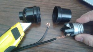
Once you have done that, you need to use either your wire strippers (or exacto knife) to remove enough of the black rubber sheathing to expose the copper wire underneath so that you can loop the copper wire around the socket terminals.
In the photo above, you can see the exposed copper wires and the terminals (screws). We recommend twisting the copper wires together and creating a loop as shown and then wrapping them around the screws and tightening them down.
Make sure you attach the correct wire to the correct terminal.
The smooth strand of the lamp wire is the hot wire. The brass (gold colored) screw terminal is the hot terminal. So the smooth wire connects to the gold colored terminal. And then the ribbed wire goes to the silver terminal.
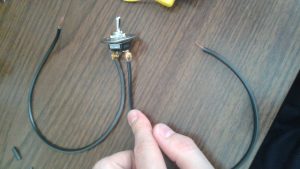
One you’ve connected the wires to the base of the socket, you can put the black light socket back together and pull the wires tight, with the wire going from the terminals on the base of the black socket, back through the pipe assembly and down to the toggle switch.
Here is the toggle switch that we use.
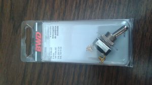
You can use other toggle switches as long as you can fit it inside of the pipe once wired.
Remove the nut from the front of the toggle switch and remove the on/off faceplate, slide the washer on and then replace the nut and faceplate.
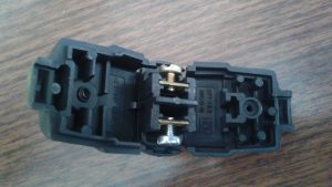
To install the toggle switch, you need to cut a piece of wire (about 6-8” in length) and separate the wires. Take each strand of separated wire and strip each end of the wire as you did before when attaching it to the terminals on the black light socket.
Attach one strand of wire to the top terminal of the toggle switch and attach the other strand of wire to the bottom of the toggle switch.
We recommend shielding the terminals and wires with electrical tape and or the ½” split plastic wire shielding as pictured below. (Only one wire is shown as shielded below, we recommend shielding BOTH terminals.)
You can hold both sections of ½” split plastic in place by wrapping electrical tape around it.
Once you have properly insulated the terminals with electrical tape and the ½” split plastic, pull the wire thru the rest of the lamp assembly.
Make sure you label the wire that goes from the top “ON” side of the terminal somehow.
To hold the washer against the pipe coupling use a few generous dabs of JB weld and hold it in place until it sets. (Make sure you have the toggle switch faceplate oriented properly so the ON portion of the faceplate is facing up.)
Once you have the toggle switch installed, it’s time to wire it into the lamp wire that goes back to the light socket.
In order to do this, you need to cut ONLY the hot wire coming back down thru the pipe from the lightbulb socket. So cut the hot wire in half and pull each of the severed ends of the hot lamp wire away.
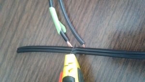
Cut it as shown in the picture and then attach the “ON” side to the section of the lamp wire that is higher up. In the photo, this would mean attaching the wire that has the green marker on it to the section of the hot wire running to the left of the knife.
The picture above is just for illustrative purposes only, but in reality the section to the left of the knife would be going back up through the rest of the pipe back up to the black light socket. The section of wire on the right of the knife would go back down through the rest of the pipe and out the bottom of the harmonic balancer.
Once you’ve connected the “ON” section of wire from the toggle switch to the upper side of the hot wire, you now need to connect the “OFF” section of wire from the toggle switch to the lower side of the hot wire.
So in this case, you would be connecting the wire from the toggle switch that isn’t labelled with green tape to the other HOT section of the wire that was cut to the right of the knife.
Once you’ve connected these sections, it’s important to insulate the connections. You can do this using maretts, or wrapping the connections in black electrical tape. Or both. Just make sure that you wrap each connection individually.
Remember: if you mess this up and burn your house down or electrocute yourself it’s on you 🙂 if you aren’t sure about doing this seek qualified advice.
Once you’ve done that, we recommend shielding both connections using the ½” split plastic and then fixing it in place using black electrical wire.
Once you’ve done this, you are ready to connect the harmonic balancer.
So run your pipe parts down and through the harmonic balancer and use a floor flange to connect the pipe assembly to the harmonic balancer.
Once you’ve done that you can begin drilling out the harmonic balancer to fit the hole pattern of the floor flange.
The harmonic balancers that we’ve used have always had 3 threaded holes in them. If this is the case, start by drilling out (removing) the threads by using the ¼” drill. If your harmonic balancer doesn’t have any holes, you will have to drill thru one of the holes in the floor flange up thru the harmonic balancer before you can drill the other holes.
Once you’ve drilled out one of the threads, put one of the ¼” flathead bolts through the floor flange and put the nut on the other end as shown in the picture below.
The one bolt will now hold the floor flange in place and while you drill out the other threads.
Now drill through the threads in the other two holes all the way thru the ¾” floor flange on the bottom.
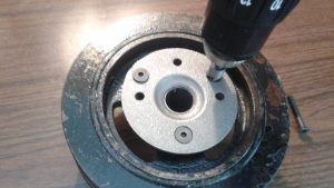
Once you have all three holes drilled out and thru the floor flange, it’s time to countersink the bottom of the floor flange as shown below.
We recommend taking out one bolt to countersink at a time. The two remaining bolts will hold everything in place as you countersink it. Make sure to countersink the hole enough so that the ¼” flathead bolt sits flush with the floor flange.
Once you have countersunk all the holes, install the nuts and bolts and then run the rest of the wire thru the assembled harmonic balancer and floor flange and then screw the pipe assembly together complete the lamp assembly.
Once you’ve done this, you can install felt pads to the bottom of the harmonic balancer to keep it from scraping any surfaces the lamp sits on, and to raise the harmonic balancer high enough to allow the lamp wire to pass underneath the lamp.
The final step is wiring the end plug.
To do this, separate the 2 strands of lamp wire as you have done before and remove enough of the sheathing so you can loop it around the terminals as you’ve done before.
This is the socket that we typically use and it’s an easy wire plug by Leviton.
Wire the plug just as you did the lamp socket, with the smooth wire connecting to the brass screw terminal and the ribbed wire connecting to the silver screw terminal.
Once you’ve done that, you can install your LED light, plug in your lamp, turn it on and enjoy!
If it doesn’t work, make sure that you’ve wired it correctly and are using the proper light socket and compatible LED lightbulb.
We recommend only using LED lights as they emit less heat. With regular lights, we have found that the heat they give off can cause the valve cover, the semi-gloss clearcoat and the pipe to off-gas a bit where they give off some fumes.
So to avoid that (and save energy) we recommend only using LED lights.
And there you have it – a completely unique, hand-made lamp.
Conclusion
We hope that you’ve enjoyed this “how to” project and that you’ve been able to successfully create your own lamp.
In doing this or any other DIY project, it’s important to take your time and be safe. If you get frustrated, it’s best to leave the project for a bit and come back to it later once you’ve cooled off.
With a little patience and practice you can make an incredible looking lamp like these too!
Leave a Reply